
Leveraging CAD/CAM for Precision Metal Manufacturing: A Designer's Guide (As of 2026-11-17)
In the intricate world of modern metal manufacturing, the pursuit of unparalleled precision and efficiency is constant. For designers and engineers, bridging the gap between a complex digital model and a flawlessly produced physical component often presents a significant challenge. This is where Computer-Aided Design (CAD) and Computer-Aided Manufacturing (CAM) become indispensable. These integrated technologies represent the backbone of contemporary CAD/CAM metal manufacturing, enabling the creation of components with exacting specifications and consistent quality, redefining what's possible in metal fabrication.
Historically, metalworking relied heavily on manual drafting and skilled craftsmanship. While artful, this approach was time-consuming, prone to human error, and struggled with the reproducibility required for mass production or highly complex geometries. The advent of CAD/CAM systems has fundamentally transformed this landscape, providing a digital ecosystem where designs are conceived, refined, and translated directly into machine instructions, ensuring that every cut, bend, or drill is executed with digital precision.
What is CAD/CAM and Why is it Essential for Metal Manufacturing?
To truly grasp their impact, it's crucial to understand CAD and CAM individually before appreciating their synergy.
Defining Computer-Aided Design (CAD): Visualization and 3D Modeling
Computer-Aided Design (CAD) refers to the use of specialized software to create, modify, analyze, or optimize a design. For metal manufacturing, CAD software allows designers to construct detailed 2D drawings and sophisticated 3D digital models. These models aren't just visual representations; they contain comprehensive data about a part's geometry, dimensions, material properties, and structural integrity. This digital blueprint serves as the definitive reference point for everything that follows, ensuring that every aspect of the component is precisely defined before any physical material is processed. Modern CAD platforms offer robust tools for intricate surfacing, solid modeling, and assembly design, allowing for the creation of components ranging from simple brackets to complex aerospace parts.
Defining Computer-Aided Manufacturing (CAM): Translating Design to Production
Computer-Aided Manufacturing (CAM) is the process of using software to prepare a digital CAD design for physical production. Once a design is finalized and approved in CAD, CAM software takes over. Its primary function is to translate the CAD model into detailed, machine-readable instructions, known as G-code and M-code, for Computer Numerical Control (CNC) machines. This includes generating toolpaths—the precise routes a cutting tool will follow—defining cutting speeds, feed rates, depth of cut, and other critical parameters necessary for the chosen manufacturing process. The CAM system ensures that the physical machine interprets the digital design accurately, executing the manufacturing operations with the required precision and efficiency.
The Synergistic Power of an Integrated CAD/CAM Workflow
The true power emerges when CAD and CAM are integrated. This integration establishes a continuous, uninterrupted digital thread from design concept to final production. A designer working within an integrated CAD/CAM system can move seamlessly from modeling a part to generating the manufacturing instructions for it. This eliminates manual data transfer, reduces the potential for errors, and significantly streamlines the entire product development lifecycle. For example, a change made to a CAD model can be automatically reflected and updated in the CAM program, preventing costly mistakes and rework on the shop floor. This unified workflow is particularly vital for achieving the high precision and consistent quality demanded in advanced metal manufacturing.
Key Benefits of CAD/CAM for Precision Metal Part Design and Production
The adoption of CAD/CAM systems offers a multitude of advantages that directly contribute to heightened precision and efficiency in CAD/CAM metal manufacturing.
Unmatched Precision, Accuracy, and Repeatability
Perhaps the most significant benefit is the ability to achieve exceptional levels of precision and accuracy. CAD software allows designers to define geometries with microscopic detail. CAM then translates these details into machine movements that are repeatable down to mere microns. This ensures that every manufactured part conforms precisely to the digital design, providing consistent quality across entire production runs, whether creating a single prototype or thousands of identical components. This level of control is virtually impossible to achieve through manual methods alone.
Optimizing Material Use Through Advanced Nesting
Material costs often represent a substantial portion of manufacturing expenses. CAD/CAM systems, particularly those with advanced nesting features, play a critical role in optimizing material utilization. Nesting algorithms efficiently arrange multiple parts onto a single sheet or plate of raw material, minimizing the amount of scrap or off-cut waste. This intelligent layout can lead to significant cost savings by reducing material consumption and streamlining the cutting process. For companies processing large volumes of materials, such as those working with heavy gauge plate or specialized Alloy Steel, these optimizations can translate into substantial economic benefits.
Accelerated Prototyping and Production Cycles
The digital workflow inherent in CAD/CAM dramatically shortens the time from concept to completion. Designers can rapidly iterate on designs, simulate manufacturing processes, and make adjustments virtually. Once a design is finalized, CAM quickly generates machine code, allowing for immediate production. This acceleration is crucial for rapid prototyping, where new designs need to be tested and refined quickly, as well as for meeting tight production deadlines in high-volume manufacturing environments.
Enhanced Visualization and Pre-production Validation
CAD software provides extensive capabilities for visualizing a design from all angles. Designers can not only see a 3D model but also analyze its structure, identify potential design flaws, and ensure all components fit together correctly in an assembly. This virtual validation process helps catch errors early in the design phase, before any material is cut. This proactive identification of issues prevents costly rework and scrap, improving overall project efficiency.
Core CAD/CAM Capabilities and Supported Fabrication Processes
CAD/CAM systems are incredibly versatile, supporting a wide array of metal fabrication techniques. Their core strength lies in translating complex digital information into actionable instructions for diverse machinery.
From 2D Drawings to Complex 3D Models
While 2D CAD remains essential for many applications, modern CAD systems excel at creating complex 3D solid and surface models. These capabilities are crucial for designing intricate parts with non-linear geometries, internal features, or those requiring multi-axis machining. The ability to model in three dimensions allows for a comprehensive understanding of the part's form and fit, which is critical for precision metal components.
CNC Cutting Technologies: Laser, Waterjet, Plasma, Oxy-fuel, Punching
For flat sheet metal and plate processing, CAD/CAM drives various CNC cutting technologies:
- CNC Laser Cutting: Offers high precision and a clean cut for intricate shapes in various metal thicknesses, from thin foils to thick plates of Steel 1018.
- CNC Waterjet Cutting: Ideal for heat-sensitive materials or very thick metals, providing a smooth edge without thermal distortion.
- Plasma and Oxy-fuel Cutting: Used for thicker metal plates, offering faster cutting speeds for robust applications.
- Punching: Automated punching machines, driven by CAM, can rapidly create holes and shapes in sheet metal using a turret of tools.
CNC Machining: Milling, Turning, and Multi-Axis Operations
CAM is foundational to CNC machining, which involves removing material from a workpiece to create the desired shape. This includes:
- CNC Milling: Utilizes rotating cutting tools to remove material from a stationary workpiece, capable of producing complex 3D shapes.
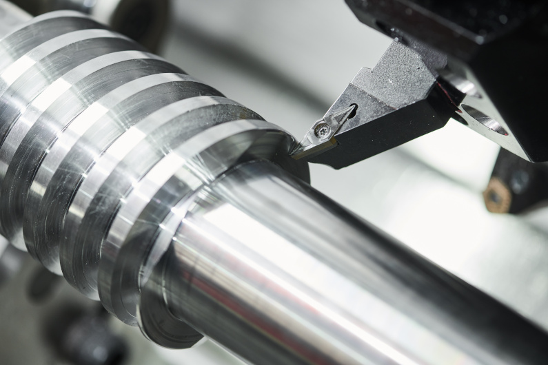
- CNC Turning: Involves rotating the workpiece against a stationary cutting tool, typically for cylindrical parts.
- Multi-Axis Operations: Advanced CAM systems can program 3-axis, 4-axis, and 5-axis CNC machines, allowing for the creation of highly complex geometries with fewer setups, enhancing efficiency and accuracy. Many
https://www.bingzhen-sh.com/cnc-machining-service/providers leverage this capability to produce intricate parts.
Precision Forming and Bending: Press Brakes and Beyond
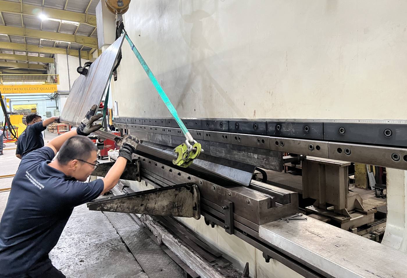
For bending and forming sheet metal, CAM software generates precise bend programs for CNC press brakes. This ensures consistent bend angles and radii, essential for assemblies where multiple bent parts must fit together perfectly. Beyond press brakes, CAM can also drive specialized forming equipment for hydroforming or roll forming.
Specialized Applications: Tube Processing and 5-Axis Cutting
CAD/CAM extends to more specialized applications, such as laser cutting and bending of tubes and profiles, where complex geometries require sophisticated 3D programming. Furthermore, 5-axis cutting, whether laser or waterjet, enables the creation of parts with bevels, complex contours, and undercuts that would be impossible with traditional 2D cutting methods.
Essential CAD/CAM Software and Tools for Designers Today
The market offers a diverse range of CAD and CAM software, each with unique strengths. Designers must select tools that best fit their specific needs and the complexity of their metal manufacturing projects.
Leading CAD Platforms for Metal Design
Common CAD platforms widely used in metal manufacturing include industry standards like Autodesk AutoCAD and Fusion 360, SolidWorks, PTC Creo, and Siemens NX. These platforms provide robust modeling environments, extensive libraries of standard components, and features for design analysis and simulation. They allow designers to create precise digital models, ensuring every detail is accounted for before manufacturing begins.
Advanced CAM and Nesting Solutions
On the CAM side, solutions like OMAX Layout, ProNest LT, BySoft, and Almacam specialize in generating efficient toolpaths and optimizing material use through advanced nesting algorithms for various cutting and forming processes. These tools are critical for translating complex CAD geometries into precise machine instructions, minimizing material waste, and maximizing throughput.
Choosing the Right Software for Your Manufacturing Needs
The choice of CAD/CAM software often depends on the specific types of metal parts being manufactured, the machinery available, and the desired level of integration. Some businesses prefer integrated suites that offer both CAD and CAM functionalities, while others opt for best-in-class standalone solutions for each discipline, connected through data exchange formats. The goal is always to find a solution that enhances workflow, improves precision, and supports the specific fabrication processes utilized.
Implementing CAD/CAM: From Customer Concept to Finished Metal Component
The journey of a metal component, from a customer's initial concept to a finished product, is meticulously managed through the CAD/CAM workflow, ensuring precision at every stage.
The Design-to-Manufacture Workflow: A Step-by-Step Guide
- Concept & Design: A customer provides a concept or specification. The designer uses CAD software to create a detailed 2D drawing or 3D model, incorporating all functional and aesthetic requirements.
- Design Validation: The CAD model undergoes analysis for structural integrity, manufacturability, and assembly fit. Any issues are addressed in this digital phase.
- CAM Programming: Once the CAD design is approved, it's imported into CAM software. The CAM programmer defines the manufacturing process, selects tools, generates toolpaths, and simulates the machining process to identify potential collisions or inefficiencies.
- Machine Code Generation: The CAM system generates the G-code and M-code, which are the instructions that directly control the CNC machine.
- Setup & Production: The CNC machine is set up with the correct raw material and tooling. The generated machine code is loaded, and the manufacturing process begins, meticulously crafting the metal component.
- Quality Control: Post-production, the finished part undergoes rigorous quality checks using precise measurement tools, sometimes integrated with the digital design for comparative analysis.
Protecting Your Intellectual Property in a Digital Workflow
In a highly competitive environment, protecting intellectual property (IP) is paramount. CAD/CAM systems, by keeping designs digital and traceable, offer inherent advantages in IP protection. Secure digital storage, access controls, and version tracking within CAD/CAM platforms help safeguard proprietary designs. Companies can also implement strict protocols for data sharing and ensure that digital assets remain within controlled environments, such as on the main company website like https://www.bingzhen-sh.com/, rather than being exposed to external risks.
Industries Transformed: Where Precision CAD/CAM Makes the Difference
The impact of CAD/CAM in metal manufacturing extends across a vast spectrum of industries, enabling innovations and production efficiencies in critical sectors.
Aerospace, Defense, and High-Performance Components
These industries demand the highest levels of precision, reliability, and material strength. CAD/CAM is indispensable for designing and manufacturing complex turbine blades, airframe components, intricate brackets, and specialized weaponry, where tolerances are measured in microns and performance cannot be compromised.
Automotive, Transportation, and Heavy Equipment
From engine blocks and chassis components to body panels and specialized parts for construction machinery, CAD/CAM drives the production of consistent, high-quality metal parts. It facilitates the creation of complex molds for casting, precise stamping dies, and intricate machined components for vehicle systems.
Industrial Manufacturing and OEM Production
Original Equipment Manufacturers (OEMs) and industrial manufacturers rely on CAD/CAM for producing everything from machine tool components and robotic parts to factory automation equipment. The ability to customize and produce parts with high repeatability is critical for maintaining robust supply chains and product quality.
Medical Devices and Semiconductor Industries
In medical device manufacturing, CAD/CAM produces sterile, biocompatible implants, surgical instruments, and diagnostic equipment with extremely fine features and tight tolerances. Similarly, the semiconductor industry uses CAD/CAM to create ultra-precise components for chip manufacturing equipment, where nanoscale accuracy is often required.
Custom Fabrication, Job Shops, and Rapid Prototyping
Small to medium-sized custom fabrication shops and job shops leverage CAD/CAM to handle diverse projects, from custom architectural elements to one-off replacement parts. For rapid prototyping, CAD/CAM enables quick design iterations and efficient production of functional prototypes, accelerating product development cycles across all industries.
Frequently Asked Questions
What is CAD and CAM in manufacturing?
CAD (Computer-Aided Design) involves using software to create 2D drawings and 3D digital models, defining the shape, dimensions, and structural integrity of a desired part. CAM (Computer-Aided Manufacturing) then takes this approved digital design and translates it into machine-readable instructions, toolpaths, and programs for automated CNC (Computer Numerical Control) production. Together, they create a seamless digital workflow from design to physical creation.
Conclusion
The journey through the capabilities of CAD/CAM for precision metal manufacturing reveals a landscape transformed by digital innovation. These technologies are no longer just tools but integrated systems that empower designers to push the boundaries of complexity and achieve unprecedented levels of precision. By understanding the symbiotic relationship between CAD and CAM, and leveraging their advanced features, designers can streamline workflows, minimize errors, optimize material utilization, and significantly accelerate the path from concept to a perfectly realized metal component. As you continue to navigate the demands of modern manufacturing, exploring specialized training in CAD/CAM software and staying abreast of advancements in automated production techniques will be invaluable for further enhancing your capabilities.
