
DFM for Sheet Metal Fabrication: Cost-Saving Strategies for 2026
Designing a sheet metal part often appears straightforward in a CAD environment, where complex geometries can be rendered with ease. However, the true test of a design lies not just in its functionality or aesthetic appeal, but in its manufacturability. Engineers frequently encounter situations where a seemingly perfect design proves prohibitively expensive, time-consuming, or even impossible to fabricate using standard sheet metal processes. This discrepancy arises from a lack of Design for Manufacturability (DFM) for sheet metal fabrication, a critical approach that integrates manufacturing considerations directly into the design phase.
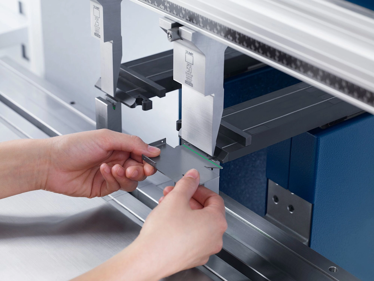
DFM is a proactive engineering methodology that optimizes product design for ease of manufacturing, aiming to reduce production costs, improve quality, and accelerate time-to-market. For sheet metal fabrication, this means understanding the capabilities and limitations of processes like cutting, bending, forming, and welding, and then applying that knowledge to create designs that are inherently efficient to produce. Ignoring DFM principles can lead to unexpected tooling costs, increased material waste, longer cycle times, and a higher incidence of defects, all of which inflate the final product cost.
The Core Principle of Design for Manufacturability in Sheet Metal
At its heart, DFM for sheet metal is about anticipating potential manufacturing challenges and addressing them on the drawing board rather than on the factory floor. This forward-thinking approach is fundamental because the decisions made during design have a disproportionate impact on overall production costs. When designers understand how metal behaves under stress, how various machines operate, and the cost implications of different geometries, they can make informed choices that streamline the entire fabrication process.
Consider the journey of a sheet metal part: it begins as a flat sheet, undergoes cutting, then bending or forming, and possibly welding or assembly before finishing. Each step has specific requirements and constraints. A design that overlooks these details might demand specialized tooling, multiple complex setups, or excessive material handling, all of which add expense. By embedding DFM, designers aim for simplicity, standardization, and efficiency, ensuring that the part can be produced consistently, reliably, and at the lowest possible cost. This doesn't mean compromising on functionality or performance, but rather achieving them through methods that align with manufacturing realities.
Strategic Considerations for Sheet Metal Material and Cutting
The initial stages of sheet metal fabrication involve selecting the right material and then cutting the flat pattern. DFM principles applied here focus on minimizing waste, ensuring part integrity, and optimizing cutting efficiency.
Material Selection and Grain Direction
Sheet metal acquires a "grain" during the rolling process, akin to wood grain. This grain significantly influences the material's ductility and its behavior during bending. Bending perpendicular to the material grain generally reduces the risk of cracking, especially for less ductile materials or those that have undergone heat treatment. Conversely, bending parallel to the grain can induce micro-cracks or even full fractures. Designers should specify preferred bend directions relative to the grain where critical, or design parts that can accommodate bends in either orientation for greater manufacturing flexibility. For example, materials like 6061-T6 aluminum often require bends to be made perpendicular to the grain, with a larger bend radius to prevent cracking. Understanding properties of different metals, such as Steel 1018, can further inform design choices related to material behavior during forming.
Optimizing Cutting Processes
Different cutting technologies—laser, waterjet, and punch press—each have distinct DFM implications:
- Laser Cutting: Offers high precision and excellent edge quality, making it suitable for intricate geometries and medium-volume production. Designers should be aware of the kerf width, typically 0.75-1.0mm (0.030-0.040 inches), and design features accordingly. Parts should be nested efficiently to minimize material waste.
- Waterjet Cutting: Extremely versatile, capable of cutting almost any material without a heat-affected zone. Tolerances can vary significantly (±0.002 inches to ±0.020 inches) depending on nozzle condition and machine upkeep. Designers should specify tolerances commensurate with waterjet capabilities to avoid over-engineering.
- Punch Press: Most economical for high-volume production, especially for parts with many standard holes or simple shapes. It relies on dies, so using standard hole sizes and common patterns significantly reduces tooling costs and lead times. Designers should avoid internal corners with small radii when designing for punching, as these require specific, often expensive, tooling.
DFM for Holes, Slots, and Narrow Cutouts
The placement and dimensions of features like holes and slots are critical. Holes should be placed a minimum of 1.5 times the material thickness away from any edge and approximately 2 times the material thickness apart from other holes. When placing holes near bends, a general guideline is to maintain a distance of at least 2.5 times the material thickness plus one bend radius from the bend line to prevent distortion or tearing during forming. Slots should generally be wider than the material thickness, and positioned at least 2 times the material thickness from edges and 4 times the material thickness from bends. Adhering to these guidelines ensures structural integrity and reduces the likelihood of cracks or deformations during processing, ultimately contributing to a more efficient and less costly Sheet Metal Fabrication Service.
Mastering Bending and Forming: DFM Guidelines for Optimal Results
Bending is one of the most common operations in sheet metal fabrication, transforming flat blanks into three-dimensional components. Poor design choices in this area are a frequent source of manufacturing difficulties and cost overruns.
Achieving Optimal Bend Radii and Bend Allowance
A fundamental DFM rule for bending is to specify an inside bend radius that is appropriate for the material and its thickness. For ductile materials, an inside bend radius at least equal to the material thickness is generally recommended. For less ductile materials, such as 6061-T6 aluminum, the minimum inside bend radius may need to be as much as 4 times the material thickness to prevent cracking. Using a consistent, standard bend radius across a design, or even across a family of parts, allows fabricators to utilize standard tooling, which significantly reduces setup time and tooling costs. Conversely, requiring unique or very tight radii for every bend can necessitate custom tooling and multiple setups, driving up expenses.
The Critical Role of Bend Relief
When a bend is made close to an edge or other features, the material can tear or deform unevenly, leading to stress concentrations. To prevent this, designers should incorporate bend relief – a small cut-out at the junction of a bend and a flat edge. This cut-out allows the material to deform in a controlled manner during bending, improving the integrity of the part and preventing material distortion. A common guideline suggests a bend relief width greater than or equal to half the material thickness, extending beyond the bend line.
Understanding and Managing Material Springback
Metals possess elasticity, meaning they will "spring back" slightly after a bending operation. This phenomenon, known as springback, means that the final angle of a bent part will be slightly different from the angle of the bending tool. Designers should account for springback by specifying flexible tolerances for bend angles where possible, rather than rigid, overly precise angles (e.g., specifying 90° ± 1° instead of 90.00°). Overly strict angular tolerances can lead to costly rework, additional tooling adjustments, and increased inspection times. Fabricators typically compensate for springback by over-bending the material, but this compensation is more consistent with flexible design tolerances.
Designing for Adequate Flange Lengths
Flanges are the bent-up sections of a sheet metal part. For efficient bending, flanges must be long enough for the manufacturing equipment (e.g., press brake dies) to securely grip the material. A common guideline suggests a minimum flange length of at least 4 times the material thickness. Flanges that are too short may require specialized, custom tooling or additional, complex setups, increasing manufacturing costs. Designers should also consider the overall geometry and ensure sufficient clearance for tooling around the flanges to prevent interference.
Enhancing Efficiency Through Smart Feature Design
Beyond the basics of cutting and bending, the precise design and placement of other features can significantly influence manufacturing efficiency and cost.
Placement and Spacing of Holes, Slots, and Tabs
As noted, strategic placement prevents distortion. For instance, maintaining sufficient distance between holes (approximately 2 times the material thickness) avoids weakening the material. Tabs, often used for interlocking components or for assembly, should have a width of at least 2 times the material thickness to ensure they are robust enough for handling and subsequent assembly operations without deforming or breaking. Careful consideration of these dimensions reduces waste and ensures part reliability.
Incorporating Stiffeners for Structural Integrity
Thin sheet metal panels can be prone to vibration or deflection. Incorporating simple stiffening features, such as beads, ribs, or flanges, can dramatically increase the bending and torsional stiffness of a part without adding significant material or weight. Designing these directly into the sheet metal avoids the need for secondary operations like welding on separate stiffeners, thereby reducing complexity and cost.
Maximizing the Use of Standard Tooling and Components
One of the most impactful DFM strategies for cost reduction is to design parts that can be fabricated using readily available, standard tooling and components. This applies to bend radii, hole sizes, and even common forming processes. Custom tooling—whether for a unique bend, an unusual hole shape, or a specialized forming operation—is expensive and adds lead time. By designing with standard tooling in mind, manufacturers can reduce setup times, avoid capital investment in new equipment, and achieve faster production cycles. This directly translates into lower unit costs and quicker delivery. When selecting materials, opting for common Sheet Metal Materials also contributes to this goal, ensuring easier sourcing and often lower material costs.
Tolerance Management: When Precision Matters (and When it Doesn't)
Overly tight tolerances specified for non-critical features can significantly increase manufacturing costs. Each decimal place of precision added to a dimension typically correlates with a higher manufacturing effort, more expensive machinery, increased inspection time, and potentially more scrap. Designers should clearly distinguish between critical dimensions that require tight tolerances for functionality or assembly, and non-critical dimensions where looser tolerances are acceptable. This selective approach allows manufacturers to allocate resources efficiently, focusing precision where it is truly needed and relaxing it where it is not, thereby optimizing costs without sacrificing performance.
Translating DFM Principles into Tangible Cost Savings
Implementing DFM for sheet metal fabrication is not merely a collection of rules; it's a strategic approach that yields significant financial and operational benefits. The cumulative effect of these design choices directly impacts the bottom line.
By adhering to DFM guidelines, you can anticipate and mitigate common manufacturing issues:
- Minimizing Reworks and Material Waste: Correct bend radii, proper feature placement, and suitable material grain orientation prevent cracking, distortion, and scrap. This reduces the need for expensive re-cutting or re-forming operations.
- Streamlining the Design Review Process: Designs inherently optimized for manufacturing require fewer iterations and corrections during reviews, shortening the design cycle.
- Reducing Production Cycle Times: Using standard tooling, avoiding complex setups, and ensuring easy-to-form geometries leads to faster machine operation and quicker overall production.
- Lowering Tooling Costs: Standardized features eliminate the need for costly custom dies and punches, which can be a significant upfront expense.
- Improving Part Quality and Consistency: Designs that account for manufacturing realities result in parts that are more consistent in quality, with fewer defects.
Ultimately, integrating DFM is about fostering a collaborative relationship between design and manufacturing. Early engagement with fabricators can provide invaluable insights into practical manufacturing constraints and opportunities. Accessing resources like www.bingzhen-sh.com can offer further guidance on best practices in various aspects of sheet metal design and production. This collaborative mindset, combined with a deep understanding of manufacturing processes, transforms sheet metal designs from theoretical concepts into cost-effective, high-quality physical products.
Frequently Asked Questions
What are the DFM guidelines for sheet metal fabrication?
DFM guidelines for sheet metal fabrication encompass a broad range of considerations aimed at optimizing designs for cost-effective production. These include selecting appropriate materials with regard to their ductility and grain direction, choosing efficient cutting processes, ensuring proper placement of holes, slots, and tabs relative to edges and bends, and designing for optimal bend radii and bend relief. Additionally, accommodating for material springback, specifying adequate flange lengths, and leveraging standard tooling are crucial for streamlining the manufacturing process.
Why is material grain important in sheet metal bending?
The grain of sheet metal, a result of its rolling process, dictates its ductility and susceptibility to cracking during bending. Designing bends perpendicular to the material grain minimizes the risk of material failure and ensures stronger, more reliable parts, particularly for heat-treated or less ductile metals like certain aluminum alloys. Ignoring grain direction can lead to material fatigue, cracking, and ultimately, part rejection, increasing overall production costs.
What are the common mistakes to avoid when designing sheet metal bends?
Common mistakes in designing sheet metal bends include specifying insufficient bend radii, placing holes or slots too close to bend lines, omitting necessary bend relief, and designing flanges that are too short for tooling to grip effectively. Other errors involve neglecting to account for material grain direction when designing critical bends and failing to allow for material springback, which can lead to parts not meeting their intended angles.
How do specific design choices impact the cost of sheet metal parts?
Specific design choices significantly impact the cost of sheet metal parts by influencing tooling requirements, material usage, process complexity, and the potential for rework. For instance, using non-standard bend radii or hole sizes necessitates expensive custom tooling. Inefficient material nesting leads to more scrap, while overly tight tolerances for non-critical features increase inspection and production costs. Conversely, designing with standard features, efficient material layouts, and practical tolerances reduces expenses and accelerates production.
Conclusion
The complexities of sheet metal fabrication demand more than just functional design; they require thoughtful consideration of how a part will be brought to life. By embracing Design for Manufacturability for sheet metal fabrication, designers can move beyond theoretical concepts to create components that are not only fit for purpose but also optimized for efficient and economical production. The actionable strategies discussed – from material selection and cutting process considerations to precise bending guidelines and feature placement – collectively contribute to a streamlined manufacturing workflow and significant cost savings. For those involved in product development, a deeper exploration of these principles and continued collaboration with manufacturing experts will be key to unlocking maximum value and innovation in sheet metal part design.
