
Mastering Precision Offset Bending for Complex Sheet Metal Designs (2026 Guide)
When fabricating intricate sheet metal components, few challenges are as persistent as achieving consistent, accurate offset bends. If you've ever found yourself battling springback, struggling with mismatched flanges, or debating the investment in specialized tooling versus the compromises of standard setups, you understand the frustration. Precise offset sheet metal bending is often the key to seamless assembly and optimal product performance, yet the path to mastering it can seem fraught with technical complexities and critical purchasing decisions. This guide cuts through the noise, offering a buyer's perspective on how to achieve flawless Z-bends, whether you're selecting the right equipment, tooling, or external fabrication services.
What is Offset Bending? Understanding Z-Bends in Sheet Metal
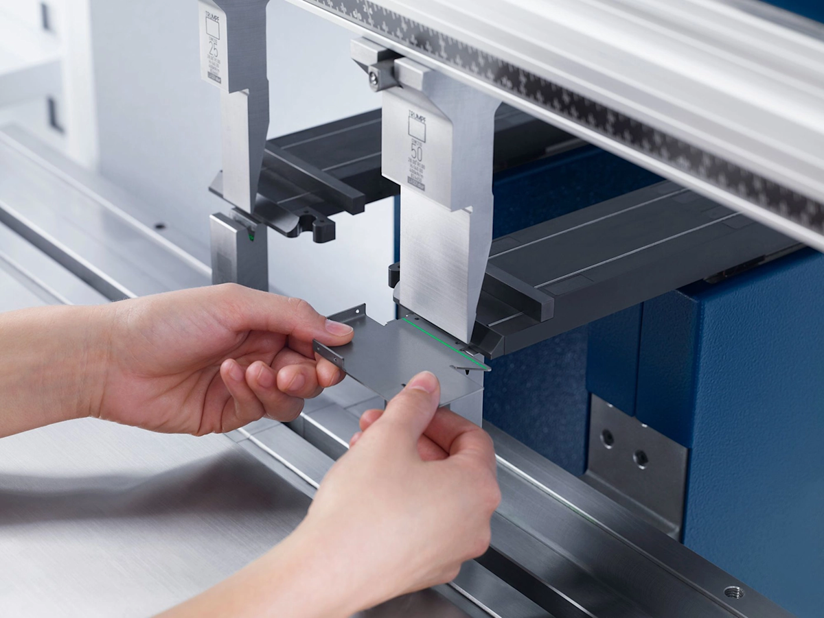
Offset bending, often referred to as Z-bending, is a fundamental sheet metal forming process that creates two parallel bends in opposite directions within a single workpiece, forming a distinctive Z-shaped profile. This technique is indispensable for designs where components need to align at different planes, creating clearances for internal parts, or providing structural rigidity in a compact form factor. Think of it as creating a miniature staircase within a flat sheet, allowing subsequent parts to be mounted at a different elevation without requiring welding or additional fasteners.
The precision of these Z-bends is paramount. Any deviation can lead to assembly issues, compromised structural integrity, or an aesthetically flawed final product. Therefore, understanding the mechanics and the available options for achieving this precision is critical for any fabricator or design engineer.
Navigating Tooling Strategies for Precision Offset Bending
The choice of tooling is perhaps the most significant purchasing decision impacting the quality, speed, and cost-effectiveness of your offset bends. Broadly, you have two primary approaches: investing in specialized dedicated tooling or optimizing the use of versatile standard tooling. Each path presents distinct advantages and disadvantages that influence your buying choices.
The One-Hit Method: Leveraging Dedicated Offset Tooling
For manufacturers dealing with high-volume production runs or projects demanding exceptionally tight tolerances on offset height, dedicated offset tooling often emerges as the superior choice. These specialized tools, comprising precisely engineered top and bottom inserts, are designed to perform both equal and opposite bends in a single press brake stroke. This "one-hit" capability dramatically increases efficiency and consistency.
Use Scenarios & Buyer Considerations:
- High-Volume Production: If your production schedule involves thousands of identical parts requiring the same offset, the speed and repeatability of dedicated tooling can lead to substantial labor savings and faster throughput, justifying the upfront investment.
- Extreme Precision: When your design specifies offset height tolerances as tight as +/- 0.005 inches, dedicated tooling is engineered to deliver this level of accuracy consistently, minimizing scrap and rework.
- Specific Offset Heights: These tools are often manufactured for a predefined offset height. Buyers must ensure the tooling matches their most frequently required offset dimensions.
- Material Compatibility: While versatile, specific dedicated tooling might perform best with certain material thicknesses or types. Consider your primary materials, such as various grades of Alloy Steel or Steel 1018, when evaluating tooling options.
Key Buying Decision: Dedicated offset tooling represents a capital expenditure that pays dividends through efficiency and precision for specialized, repetitive tasks. It’s a cleaner pick when minimizing cycle time and maximizing accuracy for specific, recurring offset geometries is non-negotiable.
The "Lazy Offset" Method: Maximizing Standard Press Brake Tooling
Not every project warrants the investment in custom-made tooling. For prototyping, low-volume production, or jobs with slightly wider tolerance allowances (e.g., +/- 0.015 inches), the "lazy offset" method using standard press brake tooling offers a cost-effective and versatile alternative. This technique involves creating offset sheet metal bending through a two-step process, leveraging the flexibility of your existing equipment.
Use Scenarios & Buyer Considerations:
- Prototyping & Low Volume: When experimenting with new designs or producing small batches, using standard tooling avoids the cost and lead time associated with custom tools.
- Versatility: Standard punches and dies can be reconfigured for a vast array of bends beyond just offsets, making them a more flexible asset for diverse fabrication needs.
- Cost-Effectiveness: The primary draw is the lower upfront tooling cost. Buyers should, however, factor in the increased labor time per part due to the two-step process.
- Operator Skill: This method requires a skilled operator to ensure consistency between the two bends. Training and experience are crucial investments here.
- Punch and Die Selection: Achieving precise results with standard tooling involves careful selection of punches and dies. A minimum 1/8-inch punch tip radius is often recommended to prevent material cracking and ensure proper geometry, especially for thicker materials.
- Machine Capabilities: Ensure your press brake's control system allows for precise angle and depth control necessary for sequential bends.
Key Buying Decision: If flexibility, lower initial investment, and handling diverse, smaller-volume jobs are your priorities, optimizing your standard tooling setup is the pragmatic choice. It demands more skill and setup time but offers unparalleled adaptability.
Achieving Precision: Key Factors and Design Considerations for Offset Sheet Metal Bending
Regardless of the tooling strategy, several fundamental principles underpin successful precision offset bending. These factors should guide both your design process and your equipment/service procurement decisions.
Material Impact: Thickness, Type, and Bend Formability
The material itself plays a pivotal role. The thickness of the sheet metal directly influences the minimum achievable bend radius and, consequently, the smallest possible offset height. Thicker materials inherently require larger bend radii to prevent cracking or excessive material thinning at the bend line. Attempting to force too small an offset on thick material can lead to structural weaknesses or outright material failure.
Different material types—such as various grades of aluminum, stainless steel, or Steel 1018—will exhibit varying levels of ductility, springback, and forming characteristics. Understanding these properties is crucial for selecting appropriate tooling, setting up the press brake, and predicting the final part geometry. When choosing materials, consider how their properties will impact the feasibility and cost of complex offset bends.
Controlling Geometry: Die Opening and Punch Tip Radius
The interaction between your punch and die is central to controlling the geometry of your offset.
- Die Opening: Selecting the correct die opening is essential. A general rule of thumb is to use a die opening that is 6 to 12 times the material thickness, depending on the material and desired bend radius. A wider die opening typically results in a larger bend radius and less tonnage required, while a narrower opening yields a sharper bend.
- Punch Tip Radius: As mentioned, for standard tooling, a minimum 1/8-inch punch tip radius is often advised to prevent stress concentrations that can lead to cracking, especially with materials prone to work-hardening. Dedicated offset tools have their punch and die geometry pre-optimized for consistent results.
Bend Relief and Springback Management
- Bend Relief: For intricate parts, especially those with features near the bend line, proper bend relief (notches or cutouts) can prevent material tearing and stress concentration. Incorporating these into your design early is crucial.
- Springback: Springback is the elastic recovery of the material after the bending force is removed. It's a critical factor in precision bending, requiring the press brake to overbend the material slightly to achieve the target angle. Modern press brakes often feature angle measurement systems and automatic springback compensation, which is a key feature to look for if you are purchasing new machinery or evaluating fabrication services.
Tolerances: Realistic Expectations for Offset Height Accuracy
As a buyer, understanding realistic tolerance expectations is vital for specifying your designs and selecting the right manufacturing partner or equipment.
| Method | Typical Offset Height Tolerance | Ideal Use Case |
|---|---|---|
| Dedicated Offset Tooling | +/- 0.005 inches | High-volume, extremely precise components |
| Standard "Lazy Offset" | +/- 0.015 inches | Prototyping, low-volume, less critical dimensions, diverse part geometries |
| Outsourced Fabrication | Varies (often +/- 0.005 – 0.010) | Complex designs, specialized materials, when internal capacity is limited |
These figures underscore that your tolerance requirements should directly influence your tooling investment or your choice of a Cnc Machining Service.
Dimensioning Offset Bends: Best Practices for Design Specifications
Clear and accurate design specifications are the bedrock of precision. When detailing offset bends:
- Specify Leg Lengths and Offset Height: Clearly define these dimensions from a common datum.
- Indicate Bend Radii: Provide the inside bend radius for both bends.
- Material Callout: Always specify the exact material type, thickness, and temper.
- Avoid Ambiguity: Provide 3D models and 2D drawings with unambiguous dimensions.
Practical Steps for Creating Offset Bends (with Standard Tooling)
For those opting for the "lazy offset" method with standard tooling, a methodical approach is key to achieving repeatable precision. This process requires careful setup and operator skill.
- Selecting Appropriate Tooling: Choose a punch with the recommended tip radius (e.g., minimum 1/8-inch) and a die with an opening suitable for your material thickness and desired bend radius.
- Setting the Press Brake: Program the press brake for the desired bend angles and setback. Accurate setup is crucial as it determines the final offset height. Calculate bend allowance and setback based on material properties and desired geometry.
- Executing the First Bend: Carefully position the sheet metal and perform the first bend. Ensure the bend is straight and at the correct angle.
- Flipping and Executing the Second Bend: Remove the workpiece, flip it, and reposition it to make the second bend parallel and opposite to the first. This step demands precision in alignment to achieve the correct offset distance. Use back gauges and side stops effectively to maintain parallelism.
- Quality Control: After bending, inspect the part using appropriate measuring tools (calipers, protractors) to verify offset height, bend angles, and parallelism. Make adjustments to the press brake settings as needed.
Tips for Optimizing Results:
- Trial Bends: Always perform trial bends on scrap material of the same type and thickness to fine-tune your press brake settings before full production.
- Consistent Clamping: Ensure the material is consistently clamped or held against the back gauge to prevent part movement during bending.
- Tooling Condition: Regularly inspect your punches and dies for wear or damage, which can lead to inconsistent bends.
Designing for Manufacturability: Optimizing Complex Offset Bends
Ultimately, mastering precision offset bending involves more than just technique; it's about making informed procurement and design decisions. Buyers must balance design intent with manufacturing capabilities and costs.
If your internal capabilities or tooling inventory cannot reliably meet the precision and volume requirements of your complex offset bends, consider partnering with a specialized fabrication service. Companies offering Cnc Machining Service often have a wide array of dedicated tooling, advanced press brakes with automatic angle correction, and experienced operators. This approach eliminates capital investment and transfers the manufacturing burden to experts. To explore the broader capabilities of such services, you might visit the main website at www.bingzhen-sh.com.
Consulting with fabricators early in the design phase can prevent costly redesigns. They can advise on optimal bend radii, material choices, and tooling strategies that simplify production and reduce costs, ensuring your complex designs are not only feasible but also efficiently manufacturable.
Frequently Asked Questions
What is offset bending?
Offset bending, also known as Z-bending, is a sheet metal forming technique that creates two parallel bends in opposite directions within a workpiece, resulting in a Z-shaped profile. This process is crucial for designs requiring components to be situated on different planes or for creating internal clearances.
How to calculate offset bend?
The specific calculation for an offset bend involves standard bend allowance and setback formulas, applied to two sequential bends. While the provided research doesn't detail exact mathematical formulas, designers typically use bend allowance charts, CAD software, or rely on iterative trial bends to determine precise press brake settings for a desired offset geometry, considering material thickness and bend radius.
What is the offset multiplier for a 30 degree bend?
The concept of a specific "offset multiplier" for a 30-degree bend is not a standard term or calculation detailed in the provided research for offset bending. Instead, the focus is on achieving a target offset height by performing two equal and opposite bends, whose individual angles might be 30 degrees, 45 degrees, or another value, depending on the overall Z-shape required.
How to bend 30 degree offset?
To create a 30-degree offset (meaning two 30-degree bends in opposite directions), you would typically use either dedicated offset tooling designed for that specific angle and offset height, or employ the "lazy offset" method with standard press brake tooling. This involves setting your press brake to produce a 30-degree bend, making the first bend, then flipping the part and making a second, parallel 30-degree bend in the opposite direction, carefully controlling the distance between the bend lines.
Conclusion
Mastering precision offset bending for complex sheet metal designs is a blend of informed decision-making, appropriate tooling selection, and meticulous execution. Whether you choose to invest in dedicated offset tooling for high-volume, hyper-accurate work, leverage the versatility of your standard press brake setup for diverse lower-volume projects, or partner with a specialized fabrication service for complex or capacity-strained needs, the key is aligning your approach with your specific project requirements and budget. If your projects frequently demand precise, high-volume offset bends, investing in dedicated tooling might be a cleaner pick due to its unparalleled efficiency and accuracy. For diverse, lower-volume needs, or when confronted with designs beyond your internal capabilities, exploring the option of a reputable Cnc Machining Service could be your most optimal approach.
