
Optimizing Sheet Metal Bending Designs for Product Development: A 2026 Guide to Best Practices
Product developers often encounter challenges when transforming a flat sheet of metal into a precisely formed component. While the concept of bending metal seems straightforward, effectively designing a part for this process demands a deep understanding of material behavior, manufacturing constraints, and geometric principles. Failing to account for these crucial sheet metal bending design considerations during the initial stages of product development can lead to costly redesigns, manufacturing delays, and parts that fail to meet performance specifications. As of 2026, advancing manufacturing technologies continue to refine best practices, making it more important than ever for designers to integrate robust bending principles from conception.
This article delves into the technical nuances behind successful sheet metal bending, explaining the underlying mechanisms and providing actionable guidelines for creating parts that are not only functional but also manufacturable and cost-effective.
The Foundational Mechanics of Sheet Metal Bending
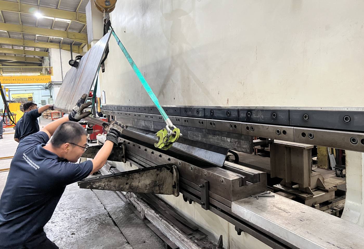
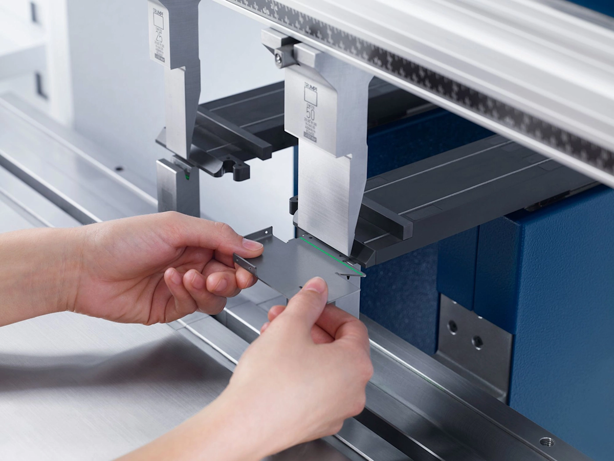
At its core, sheet metal bending is a plastic deformation process that reshapes a flat metal sheet into a desired angular form without altering its volume. This transformation occurs when localized stress exceeds the material's yield strength, causing permanent changes in its geometry. Typically, this is achieved using a press brake machine, where a punch presses the sheet into a die, forcing it to conform to the tooling's shape.
What Happens During a Bend?
When a sheet metal part is bent, the material on the outer radius of the bend stretches and elongates, while the material on the inner radius compresses. Somewhere between these two extremes lies the "neutral axis," a theoretical line where the material experiences neither tension nor compression, maintaining its original length. The precise location of this neutral axis is paramount for accurate flat pattern development, as it dictates how much the material will stretch and how long the original flat blank needs to be.
Compared to other fabrication methods like welding or riveting, bending often provides advantages in terms of part integrity and manufacturing efficiency. By forming a complex shape from a single piece of material, designers can achieve stronger, more durable components, as there are no seams or joints that could become points of failure. This can also lead to faster production times and lower assembly costs, making it a highly attractive process for low-to-medium volume production runs, typically ranging from several hundred to several thousand units per lot, where the investment in costly stamping tools is not justified.
Mastering Core Sheet Metal Bending Design Considerations
Effective design for bending starts with a thorough understanding of the geometric parameters involved and how they interact with material properties.
Critical Geometric Parameters: Bend Radius and Angle
The two most fundamental geometric parameters in sheet metal bending are the bend radius and the bend angle.
- Bend Radius: This refers to the radius of the inner surface of the bend. Specifying an appropriate bend radius is perhaps the most critical design decision. If the radius is too sharp (too small), the material can experience excessive stress, leading to cracking, tearing, or significant thinning at the bend line. Conversely, a radius that is too large might require specialized tooling or multiple bending operations, increasing costs.
- The minimum bend radius depends heavily on the material type, its temper, and thickness. For instance, ductile materials like some grades of Steel 1018 can accommodate tighter bends than harder, less ductile materials such as certain Alloy Steel compositions. As a general rule, the inside bend radius should be at least equal to the material thickness, and preferably 1.5 to 2 times the material thickness, to minimize stress and prevent cracking. For very hard or brittle materials, an even larger radius may be necessary.
- Bend Angle: This is the angle formed by the two flanges of the bent part. While common angles are 90 degrees, press brakes can create a wide range of angles. Designers must consider the tooling limitations; standard tooling is designed for common angles, and highly acute or obtuse angles may require custom tooling, adding to setup time and cost.
The K-Factor and Bend Allowance: Ensuring Flat Pattern Accuracy
Accurately calculating the flat pattern – the unbent shape of the sheet metal before forming – is essential for manufacturing. This calculation relies heavily on the concepts of the neutral axis, K-factor, and bend allowance.
- The Neutral Axis and K-Factor Calculation: As discussed, the neutral axis is the theoretical line within the material that experiences no change in length during bending. Its location is not perfectly in the center of the material thickness; it shifts slightly towards the inner radius due to compression. The K-factor is a ratio that defines the neutral axis's position relative to the material thickness. It is calculated as the distance from the inside surface of the bend to the neutral axis, divided by the material thickness (T/t).
- The K-factor typically ranges between 0.25 and 0.50, though values outside this range can occur depending on material properties, bend radius, and bending method. A K-factor of 0.33 is often used as a general starting point for many materials and applications, representing a neutral axis closer to the inner radius.
- Understanding and correctly applying the K-factor is crucial because it accounts for the material stretching and compression, directly impacting the bend allowance.
- Understanding Bend Allowance for Flat Patterns: Bend allowance (BA) is the length of the material along the neutral axis within the bend region. It is added to the lengths of the straight sections (flanges) to determine the total length of the flat pattern. The formula for bend allowance commonly incorporates the K-factor, bend angle, and bend radius.
- For air bending, where the punch does not bottom out on the die, K-factors tend to be lower when the bend radius is smaller relative to material thickness. As the bend radius increases, the K-factor generally approaches 0.50 for all materials, indicating the neutral axis is closer to the center.
- For example, for air bending with a bend radius between 0 and 1 times the material thickness (0-t):
- Soft Aluminum: K-factor ~0.33
- Hard Stainless Steel: K-factor ~0.40
- For air bending with a bend radius between 1 and 3 times the material thickness (t-3t):
- Soft Aluminum: K-factor ~0.40
- Hard Stainless Steel: K-factor ~0.45
- For bend radii greater than 3 times the material thickness (>3t), the K-factor approaches ~0.50 for most materials.
- Similar guidelines exist for bottom bending, where the K-factors generally trend higher. Accurate K-factor selection, often aided by material charts and empirical data, ensures the final bent part matches the design dimensions without needing adjustments during fabrication.
Designing for Manufacturability (DFM) in Practice
Beyond individual bend parameters, overall part geometry significantly impacts manufacturability. Integrating Design for Manufacturability (DFM) principles early in the product development cycle streamlines production and reduces costs.
Uniformity and Consistency: Material Thickness and Bend Direction
- Maintaining Uniform Wall Thickness: A critical DFM principle is to design parts with uniform material thickness throughout. Sheet metal bending operations are optimized for consistent thicknesses, typically ranging from 0.9mm to 20mm. While thicker materials (plates >3mm) and thinner materials (sheets <3mm) are both bendable, variations within a single part can complicate tooling setup and lead to inconsistent bend quality.
- Optimizing Bend Direction and Consistency: Whenever possible, design all bends in the same plane to be in the same direction. This minimizes the need for part re-orientation during the bending process, which saves time and reduces potential errors. Similarly, maintaining a consistent bend radius across all bends within a single part, or at least across different bend types, can significantly reduce tooling changes and setup costs. Utilizing a limited number of standard bend radii simplifies the fabrication process.
Feature Placement: Holes, Slots, and Notches Near Bends
Placing features too close to a bend line is a common design error that leads to distortion, tearing, or inaccurate feature placement in the final part. As the material stretches and compresses during bending, any holes, slots, or cutouts nearby will deform.
- Minimum Distance Guidelines: As a general guideline, any feature (such as a hole) should be positioned at a distance of at least twice the material thickness plus the bend radius from the bend tangent line (the point where the bend starts). For example, if the material is 2mm thick and the bend radius is 3mm, the feature should be at least (2 * 2mm) + 3mm = 7mm from the bend tangent line. This prevents deformation and ensures feature integrity.
- Countersinks vs. Counterbores: Simple features like countersinks are often feasible in sheet metal designs, as they involve minor material displacement. However, more complex machined features like counterbores are generally difficult to integrate directly before bending without risking distortion. Such complex features typically require post-machining operations, which add complexity and cost to the manufacturing process.
Flange Lengths and Bend Relief: Preventing Deformation
Two other crucial sheet metal bending design considerations for manufacturability are adequate flange lengths and the strategic use of bend relief.
- Adequate Flange Lengths: The flange is the flat portion of the sheet metal extending from the bend line. It needs to be long enough to allow the press brake tooling (punch and die) to securely grip the material during the bending operation. If the flange is too short, the material may slip, leading to an inaccurate bend angle or an improperly formed part. As a rule, the minimum flange length should be at least three to four times the material thickness plus the bend radius.
- Bend Relief: When two bends are very close to each other, especially in a corner, the material can wrinkle, tear, or pull due to overlapping stress zones. Bend relief cuts are small cutouts or notches designed to alleviate this stress and prevent material deformation. These cuts typically extend beyond the bend line into the adjacent flange, allowing the material to deform cleanly without interfering with adjacent features. Proper bend relief ensures sharper, cleaner bends and maintains dimensional accuracy, particularly in complex parts with multiple bends.
Material Properties and Their Impact on Bending Design
The choice of material fundamentally dictates what is possible in sheet metal bending. Each metal behaves differently under stress, requiring tailored design approaches.
Ductility, Grain Direction, and Springback
- Ductility: This is a material's ability to undergo plastic deformation without fracturing. Highly ductile materials (like soft aluminum or annealed copper) can tolerate tighter bend radii, whereas less ductile materials (such as high-strength Alloy Steel or hardened stainless steel) require larger bend radii to prevent cracking.
- Grain Direction: Most rolled sheet metals exhibit a grain direction, a result of the manufacturing process. Bending a sheet metal part perpendicular to the grain generally results in a stronger bend and less risk of cracking compared to bending parallel to the grain. While not always feasible, considering grain direction in the flat pattern layout can improve part quality, especially for critical bends.
- Springback: After the bending force is removed, the material partially returns to its original shape due to its elastic memory. This phenomenon is called springback. All materials exhibit springback to some degree, but its magnitude varies significantly with material type, temper, thickness, bend radius, and bend angle. Compensating for springback is crucial for achieving accurate final bend angles.
Selecting Materials for Optimal Bending Performance
Designers must select materials that balance functional requirements with bending capabilities. For example:
- Aluminum Alloys: Generally, aluminum alloys (like 5052 or 6061-T4) are highly ductile and bend well, often allowing tighter bend radii. However, they can be prone to scratching during handling.
- Stainless Steel: Many stainless steel grades (e.g., 304, 316) offer excellent corrosion resistance and strength but are stiffer and exhibit more springback than mild steel or aluminum, requiring larger bend radii and more precise compensation.
- Mild Steel (e.g., Steel 1018): This is a very common and cost-effective material, generally easy to bend with good formability and moderate springback. It's often chosen for applications where corrosion resistance is not paramount.
Always refer to material specifications and consult with fabricators for specific minimum bend radii and K-factor recommendations for the chosen material and thickness.
Advanced Considerations for Precision and Cost Optimization
Achieving precise bends and optimizing costs often involves looking beyond the basic design rules and understanding the interplay between design and manufacturing processes.
Tooling Selection and its Influence on Design Options
The specific punch and die used in a press brake operation directly influence the achievable bend characteristics. Designers should be aware of these relationships:
- V-Die Opening: The width of the V-die (the opening in the bottom die) largely determines the inside bend radius and the tonnage required for bending. A wider V-die opening generally produces a larger inside bend radius and reduces the forming pressure needed, which is beneficial for thicker materials and larger radii. However, excessively wide V-dies can lead to less precise bends.
- Punch Radius: The radius of the punch nose directly defines the minimum achievable inside bend radius. While it's possible to create a bend with an inside radius slightly larger than the punch radius (especially in air bending), the punch radius sets the lower limit. Designers should ideally specify bend radii that align with standard tooling available to the fabricator to avoid custom tooling costs and delays. Designing with a consistent, commonly available punch radius in mind for all bends simplifies tooling setup significantly.
Tolerances and Strategies for Springback Compensation
Achieving tight tolerances in bent sheet metal parts is challenging due to the inherent variability of material properties and the phenomenon of springback.
- General Tolerances: Designers must specify realistic tolerances. For common sheet metal bending, general angular tolerances are often around ±0.5° to ±1.0°, and linear tolerances ±0.2mm to ±0.5mm, depending on part size, material, and equipment. Tighter tolerances usually incur higher costs and may require secondary operations or specialized bending techniques.
- Springback Compensation: To counteract springback, several strategies are employed:
- Overbending: The most common method involves bending the material to an angle slightly beyond the target angle, so that when it springs back, it settles at the desired angle.
- Bottoming/Coining: These techniques involve pressing the material firmly into the die, often beyond its yield strength, to set the bend permanently and reduce springback. Coining essentially restrikes the bend with extreme force, plastically deforming the material throughout the bend zone.
- Material Data and Predictive Models: Modern manufacturing often utilizes sophisticated software and empirical data to predict springback more accurately for specific materials, thicknesses, and tooling combinations. This data informs the CNC programming of the press brake. Designers can assist by providing accurate material specifications.
Optimizing Design for Economic Production Volumes
While sheet metal bending is cost-effective for low-to-medium volumes, specific design choices can further enhance economic efficiency.
- Minimizing Setups and Operations: Each bend requires a setup and an operation. Designs that minimize the total number of bends, or consolidate multiple bends into a single operation (e.g., by ensuring all bends in one plane are in the same direction), reduce production time and labor costs.
- Standardizing Features: Using standard bend radii and angles, as well as maintaining consistent bend relief geometry, simplifies tooling requirements and reduces the need for custom fabrication processes.
- Material Efficiency: Designing the flat pattern to minimize material waste during cutting is a key cost driver. Efficient nesting of multiple parts on a single sheet can lead to significant material savings.
Frequently Asked Questions
What are the design guidelines for sheet metal bends?
Design guidelines for sheet metal bends include maintaining uniform material thickness, ensuring the inside bend radius is appropriate for the material (ideally 1.5-2 times thickness), and placing holes or features at a safe distance from bend lines to prevent distortion. It's also critical to provide adequate flange lengths, utilize bend relief where necessary, and account for material-specific properties like the K-factor and springback for accurate flat pattern development and consistent bend angles. Consistent bend radii across a part can also reduce manufacturing costs.
Conclusion
The successful development of products utilizing sheet metal bending hinges on a meticulous approach to design. By understanding the underlying mechanics of plastic deformation, carefully considering geometric parameters like bend radius and K-factor, and adhering to DFM principles for feature placement and consistency, designers can create parts that are robust, precise, and economically viable. The iterative nature of product development means that the insights gained from effective sheet metal bending design considerations today, as of 2026, will continue to evolve. To further deepen your expertise, exploring advanced simulation tools for predicting material behavior and springback, or delving into the specifics of various material grades, would be a valuable next step in your learning journey. For general resources and manufacturing insights, you can explore www.bingzhen-sh.com.
