
Selecting and Maintaining Press Brake Tooling for Precision Bending: A 2026 Guide
Achieving consistent, high-precision bends in sheet metal fabrication often appears to be a complex challenge, with many variables contributing to the final part quality. Among these, the choice and care of press brake tooling stand out as a foundational element, yet it is frequently underestimated or misunderstood. The correct press brake tooling selection is not merely about finding a punch and a die that fit; it is a critical engineering decision that dictates bend accuracy, angle consistency, material marking, and ultimately, production efficiency and profitability. Without a deep understanding of tooling principles, fabricators risk inconsistent results, costly material waste, and premature tool wear.
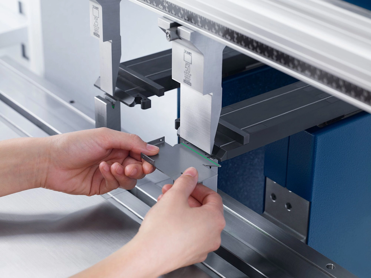
This article delves into the intricacies of selecting, setting up, and maintaining press brake tooling, providing comprehensive guidance for achieving optimal performance in sheet metal bending operations. We will explore the underlying mechanisms by which different tooling interacts with materials, highlight critical selection criteria, and outline best practices for longevity and precision, as understood in current industry practices as of 2026-11-16.
Understanding Press Brake Tooling: The Fundamentals of Punches and Dies
At its core, press brake tooling is the set of specialized instruments that physically shape sheet metal. It consists of two primary components: the upper tool, known as the punch, and the lower tool, known as the die. These two elements work in concert, applying immense force from the press brake machine to deform a flat sheet into a desired angle or profile. The punch presses down onto the material, forcing it into the cavity or opening of the die, thereby creating the bend.
The significance of optimal tooling extends far beyond simply creating a bend. It directly influences factors such as the required tonnage for bending, the internal bend radius, the likelihood of material marking, the speed of setup, and the overall lifespan of the tools themselves. An investment in high-quality, appropriately selected tooling is an investment in the precision, efficiency, and long-term profitability of a fabrication operation. When tooling is mismatched to the material or the desired bend, the press brake may struggle to deliver consistent results, leading to excessive springback, incorrect angles, or even structural damage to the tools or machine.
Navigating Press Brake Punch Selection for Diverse Applications
The upper portion of the press brake tooling, the punch, determines the inner profile of the bend and must be chosen with careful consideration of the part geometry and material. Various punch types are engineered to address specific bending challenges.
A Comprehensive Look at Press Brake Punch Types
The array of punches available reflects the diversity of bend geometries encountered in sheet metal fabrication. Understanding these types is the first step in effective press brake tooling selection:
- Standard Straight Punches: These are general-purpose tools, often featuring a standard acute angle (e.g., 88° or 85°) suitable for a wide range of basic air bends. They are versatile but limited in their ability to clear existing flanges.
- Gooseneck Punches (Swan Neck Punches): Characterized by a distinctive necked-back profile, these punches are essential for parts with deep return flanges. The setback design allows the punch to clear previously formed bends, preventing collisions and enabling more complex part geometries.
- Acute Angle Punches: With angles as sharp as 30° or 35°, these "needle tools" are used to create very sharp bends or to over-bend material to compensate for springback when forming a precise 90° angle, particularly for thicker materials or those with significant springback.
- Radius Punches: Instead of a sharp edge, these punches feature a defined radius, used specifically when a particular inside bend radius is required. This is crucial for avoiding stress concentrations in critical applications or when aesthetic considerations demand a smooth internal curve.
- Offset (Z) Punches: Designed to form Z-shaped bends in a single stroke, these tools significantly reduce setup and production time for specific part requirements, combining two bends into one operation.
- Narrow/Sword Punches: Featuring a very thin, straight profile, these punches are used for forming deep channels or bends in tight spaces where standard punches would not fit.
- Sash Punches: These are specialized punches used for forming window or door frame profiles, often creating complex multi-angle bends.
- Joggle Punches: Designed to create a slight offset or step in the material, often used for overlapping or flush assembly of sheet metal panels.
Key Considerations for Punch Selection: Material, Angle, Inside Radius, and Part Clearance
Effective punch selection is a multi-faceted process that integrates several critical factors:
- Material Type and Thickness: The properties of the sheet metal—its thickness, tensile strength, yield strength, and ductility—are paramount. Thicker or stronger materials require punches designed for higher tonnage and potentially larger radii to prevent cracking. Materials like specific grades of Steel 1018 or various Alloy Steel types will behave differently under pressure.
- Desired Bend Angle: The punch's working angle must complement the final desired bend angle. For air bending, an acute punch angle (e.g., 88°) is often used to allow for some over-bending, accounting for material springback and achieving a precise 90° or custom angle.
- Required Inside Bend Radius: The punch's tip radius directly influences the inside bend radius. Specifying the correct punch radius is vital for structural integrity and aesthetic consistency. In air bending, the inside radius is often dictated more by the V-die opening, but a radius punch can define a specific, larger radius.
- Part Clearance: This is a crucial practical consideration. The chosen punch must allow sufficient clearance to prevent collision with previously formed flanges or features on the workpiece. This is where gooseneck and narrow punches often prove indispensable.
Choosing the Right Press Brake Dies and Mastering V-Die Selection
While the punch forms the inside of the bend, the die provides the necessary support and forms the outside contour. The selection of the lower die is equally, if not more, critical for controlling bend accuracy, tonnage, and the inside bend radius.
Exploring Different Press Brake Die Types for Maximum Versatility
The lower dies come in several forms, each suited for particular bending scenarios:
- Single V-Dies: These are the most common die type, featuring a single V-shaped opening. They are highly versatile and widely used for air bending.
- Multi-V Dies: These dies consolidate several V-openings of different widths onto a single tool body. They are designed for quick changeovers, allowing operators to switch between various V-openings by simply rotating or flipping the die, thus enhancing efficiency, especially in job shops handling diverse material thicknesses.
- Two-Way Self-Centering V-Dies: These dies are designed to automatically center the material within the V-opening, which can improve accuracy and reduce setup time.
- U-Dies: Used for forming U-shaped channels, these dies have a flat bottom and vertical walls, requiring a punch that matches the U-profile.
- Hemming Dies: These specialized dies are used to flatten a pre-formed bend back onto itself, creating a safe, finished edge. This process typically involves two stages: an acute bend followed by a flattening operation.
- Channel Forming Dies: Similar to U-dies but often with wider or custom profiles for forming specific channel shapes.
- Corrugating Dies: Designed to create wavy or corrugated patterns in sheet metal.
The Critical V-Die Opening: Calculation, Impact, and the 8x Rule
The width of the V-die opening is perhaps the single most critical parameter in press brake tooling selection, especially for air bending, which is the most common method in modern fabrication. The V-die opening directly affects the inside bend radius, the required tonnage, and the precision of the bend angle.
A widely accepted rule of thumb for air bending mild steel is that the V-die opening should be 8 times the material thickness. For example, a 1mm thick sheet of mild steel would typically require an 8mm V-die opening. This "8x rule" (as validated by research on 2026-11-16) provides a good starting point to achieve an optimal balance between bend quality, tonnage requirements, and tool wear.
An incorrect V-die opening can lead to several undesirable outcomes:
- Too Narrow: A V-opening that is too small for the material thickness will concentrate excessive force, potentially leading to material cracking at the bend line, increased tonnage requirements, and accelerated tool wear. It also makes achieving a consistent bend angle more challenging.
- Too Wide: Conversely, a V-opening that is too wide can cause the material to "float" excessively, making it difficult to control the bend angle accurately. It also results in a larger inside bend radius than might be desired and can lead to inconsistent bends.
Understanding the Relationship Between V-Opening and Inside Bend Radius
In air bending, the inside bend radius is not primarily determined by the punch tip (unless using a radius punch designed to form a specific radius). Instead, it is predominantly a function of the V-die opening. As of 2026-11-16, research indicates that the inside bend radius is approximately 16% of the V-die opening. This means a larger V-die opening will naturally produce a larger inside bend radius for a given material. This relationship is crucial for design engineers and fabricators alike, as the chosen V-die opening directly impacts the structural properties and aesthetics of the final part.
How Bending Methods (Air, Bottom, Coining) Influence Die Choices
The bending method employed also dictates die selection and influences tonnage requirements:
- Air Bending: The most prevalent method for modern CNC press brakes, air bending involves pressing the material into the V-die opening without forcing it to the bottom. The bend angle is controlled by the depth the punch penetrates the die. This method requires less tonnage, is more versatile, and is gentler on tooling. Most standard V-dies and multi-V dies are optimized for air bending.
- Bottom Bending: In bottom bending, the material is pressed fully into the V-die until it contacts the die walls, forming a specific angle, often 90°. This method requires higher tonnage than air bending and can lead to faster tool wear but offers greater angle consistency, especially for less precise machines. Dies with angles matching the desired bend are typically used.
- Coining: The most tonnage-intensive method, coining involves forcing the punch deeply into the material, fully compressing and forming the bend radius and angle under extreme pressure. This method permanently sets the material, virtually eliminating springback, but it requires significantly higher tonnage (often 5-10 times that of air bending) and causes the most wear on tooling. Specialized, robust dies and punches with matching angles (e.g., 90° for coining, as noted in 2026-11-16 research) are necessary.
Essential Tonnage Calculations and Machine Compatibility
Before any bending operation, calculating the required tonnage is paramount. This ensures that the selected tooling and material are within the capacity of the press brake, preventing damage to the machine, tooling, or injury to the operator.
Performing Accurate Tonnage Calculations for Safe and Effective Bending
While specific formulas vary by material, thickness, and bending method, the principle remains: determine the force required to plastically deform the material to the desired angle. Factors influencing tonnage include:
- Material Thickness: Thicker materials require more force.
- Material Strength: Stronger materials (higher tensile strength) require more force.
- Bend Length: Longer bends require more total force.
- V-Die Opening: A wider V-die opening generally reduces the required tonnage (up to a point).
- Bending Method: Coining requires significantly more tonnage than bottom bending, which in turn requires more than air bending.
Consulting material data sheets and using press brake manufacturer guidelines or specialized software for tonnage calculations is crucial. Overloading a press brake can lead to severe damage and poses significant safety risks.
Matching Your Tooling to Press Brake Capacity and Specifications
Tooling must be meticulously matched not only to the job but also to the press brake itself. Key machine specifications include:
- Tonnage Capacity: The maximum force the machine can exert.
- Bed Length: The maximum length of the workpiece that can be bent.
- Open Height (Daylight): The maximum distance between the punch holder and the die holder, which dictates the maximum part height and the type of tooling that can be used.
- Stroke Length: The maximum travel distance of the ram, affecting how deep a bend can be formed or how high the tooling can retract for part removal.
Ensuring tooling dimensions (segment lengths, punch height, die height) are compatible with these machine parameters prevents operational bottlenecks and costly collisions.
The Role of Clamping Systems in Efficient Tool Setup
The press brake's clamping system plays a significant role in tool setup time and overall efficiency. Different systems offer varying levels of speed and security:
- Manual Clamping: Traditional and cost-effective, but requires more time and effort for tool changes.
- Semi-Automatic Clamping: Often involves hydraulic or pneumatic assistance for clamping but still requires some manual intervention.
- Hydraulic Clamping: Provides fast, secure, and precise clamping, significantly reducing tool changeover times, especially on modern CNC press brakes. Systems like Promecam or WILA are common examples.
- Pneumatic Clamping: Similar to hydraulic but uses air pressure, often for lighter tonnage machines or applications where speed is paramount.
Compatibility between the tooling tang (the part of the tool that fits into the clamping system) and the press brake's clamping mechanism is non-negotiable. Modern systems often use quick-change designs that save valuable production time. For specialized fabrication needs, consider consulting a Cnc Machining Service to ensure custom tooling fits your machine's unique clamping system.
Maximizing Tool Life: Materials, Setup, and Maintenance Best Practices
Even the best tooling will degrade without proper care. Longevity and consistent performance depend heavily on material quality, correct setup, and diligent maintenance.
The Advantage of Hardened Tool Steel and Precision Ground Tooling
High-quality press brake tooling is typically manufactured from hardened tool steel, such as 4140 or other specialized alloy steels. As of 2026-11-16, good quality tooling is often hardened to between 42-48 HRC (Rockwell Hardness C scale). This hardening process significantly enhances wear resistance, toughness, and durability, which are crucial for maintaining precision over thousands, or even millions, of bending cycles. Precision grinding ensures that the working surfaces of punches and dies are smooth, accurate, and free from imperfections, preventing material marking and ensuring consistent bend geometry. Investing in such tooling reduces the frequency of replacement and minimizes variations in part quality.
Achieving Perfect Alignment and Secure Setup for Consistent Bends
Proper tooling setup is a prerequisite for accurate and safe operation:
- Cleanliness: Always ensure that both the tooling and the press brake's clamping surfaces are free of debris, dust, and oil. Even a small particle can throw off alignment and cause uneven wear or inconsistent bends.
- Precise Alignment: Punches and dies must be perfectly aligned along the press brake's length. Modern CNC systems often assist with this, but manual checks are still vital. Misalignment leads to uneven pressure distribution, increasing tonnage requirements, causing tool deflection, and producing warped bends.
- Secure Clamping: Tools must be securely clamped into the press brake. Loose tooling is extremely dangerous and will result in inconsistent bends and damage to both the tool and the machine. Hydraulic clamping systems, for example, ensure even and powerful clamping force.
- Correct Tonnage Adjustment: Set the tonnage correctly for the material and bend. Excessive tonnage, while sometimes used to overcome springback, significantly accelerates tool wear and risks damage.
A Guide to Regular Cleaning, Lubrication, and Inspection for Tool Longevity
Regular maintenance is not just about extending tool life; it's about ensuring ongoing precision and preventing unexpected downtime.
- Cleaning: After each shift or significant job, tooling should be thoroughly cleaned to remove metal fines, lubricants, and other residues. These residues can cause pitting, corrosion, and affect bend quality.
- Lubrication: Apply a thin film of anti-corrosive oil to all tooling surfaces, especially the working edges and mounting points, before storage. This prevents rust and corrosion, which can degrade precision and lead to premature failure.
- Inspection: Routinely inspect punches and dies for signs of wear, nicks, cracks, or deformation. Pay close attention to the working edges and radii. Early detection of wear allows for reconditioning or replacement before it impacts production quality. Any visible damage, particularly cracks, warrants immediate tool removal and assessment by a qualified technician. Documenting tooling usage and inspection schedules can help predict wear patterns and plan for maintenance proactively.
Frequently Asked Questions
What is press brake tooling?
Press brake tooling comprises the upper punch and lower die that work together to shape sheet metal into desired forms during the bending process. The punch presses down, forcing the material into the die's opening, thereby creating a bend.
How do I choose the correct V-die opening for air bending?
For air bending mild steel, a commonly accepted rule of thumb (as of 2026-11-16) is to select a V-die opening that is 8 times the material thickness. This guideline helps balance bend quality, required tonnage, and tool wear.
What are the different types of press brake punches and dies?
Punch types include standard straight, gooseneck, acute angle, radius, offset (Z), narrow/sword, sash, and joggle punches, each designed for specific bend profiles or clearances. Die types commonly include single V, multi-V, U-dies, hemming dies, and channel forming dies, offering versatility for various bending requirements.
Why is proper maintenance of press brake tooling important?
Regular maintenance, encompassing cleaning, lubrication, and inspection, is crucial for several reasons. It extends the working life of the tools, ensures consistent bend accuracy, prevents premature wear or damage to both the tooling and the press brake, and ultimately maintains production efficiency and quality.
Conclusion
The selection and maintenance of press brake tooling are not incidental tasks but fundamental disciplines that underpin precision sheet metal bending. By thoroughly understanding the nuances of punch and die types, mastering V-die selection, performing accurate tonnage calculations, and adhering to rigorous maintenance protocols, fabricators can unlock the full potential of their press brake operations. The insights presented here, reflecting practices as of 2026-11-16, serve as a foundational guide. For continuous improvement, further exploration into advanced tooling materials, automated tooling systems, and specific troubleshooting techniques for challenging materials or complex part geometries would be beneficial to enhance expertise and operational excellence.
