
Sheet Metal Bending: A Buyer’s Guide to Design and Fabrication
Sheet metal bending is a fundamental process in manufacturing, transforming flat sheets of metal into three-dimensional components. This guide aims to equip buyers with the knowledge to effectively design parts for bending and collaborate with fabrication service providers. Understanding the intricacies of material behavior, design considerations, and the fabrication process itself is crucial for achieving desired part quality and functionality.
Understanding Sheet Metal Bending Processes
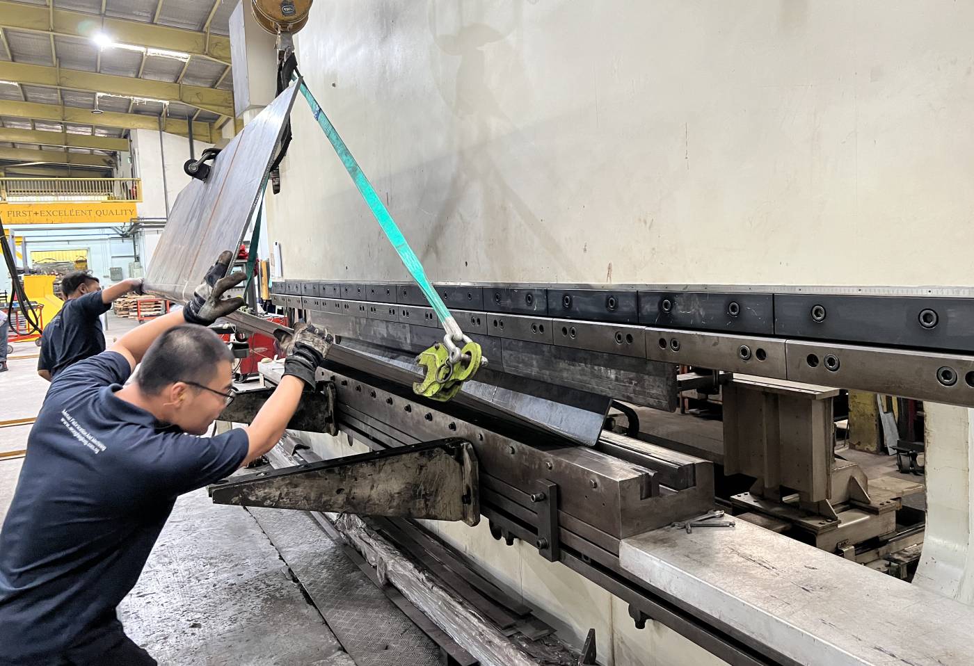
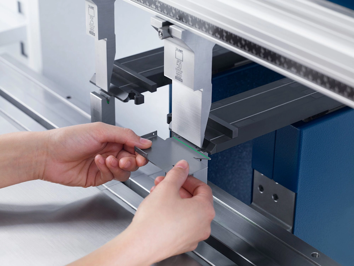
Sheet metal bending involves applying force to a metal sheet, causing it to deform along a linear axis and create a permanent bend. This process typically uses a press brake with a punch and die. The choice of bending technique, such as air bending, bottoming, or coining, offers different levels of precision and control over the bend angle and radius, often depending on the material, desired geometry, and production volume.
During bending, the material on the outer surface stretches, while the inner surface compresses. The neutral axis, where material neither stretches nor compresses, is important for calculating bend allowance. The K-factor, which helps determine the neutral axis’s position, is influenced by the material type, temper, and bending method [S3].
Key Considerations for Material Selection in Sheet Metal Bending
Material selection is a critical first step, influencing a part’s final properties, manufacturability, and cost. Buyers should consider mechanical properties like strength, ductility, and corrosion resistance, alongside aesthetic requirements and budget [S2].
Common materials for sheet metal bending include various grades of steel (e.g., mild steel, stainless steel), aluminum alloys, copper, and brass. Each material has unique characteristics affecting its bendability; some are more ductile and can be bent to tighter radii without cracking, while others may require larger bend radii or specific heat treatments. The material’s temper also plays a significant role, with softer tempers generally allowing for easier bending.
When discussing material selection with a sheet metal bending service provider, it is important to specify the exact material grade and temper. Asking the selected supplier to review the chosen material in relation to the part’s intended application and geometry can help identify potential manufacturing challenges early in the design phase [S1].
Designing for Manufacturability: Bend Radii and Relief
Properly designing bend radii and incorporating bend relief are crucial for successful sheet metal bending. The bend radius refers to the internal radius of the bend. An appropriate bend radius prevents material cracking and excessive thinning during the bending process. Generally, a larger bend radius is more forgiving and reduces stress concentrations. However, design constraints may necessitate tighter bends.
Maintaining consistent bend radii throughout a part where possible can simplify tooling and reduce setup changes during fabrication [S3]. Buyers should provide the material thickness and desired bend geometry for the selected fabricator to review, confirming feasible radii for the actual material and part [S3].
Bend relief is a cut or notch made at the intersection of a bend line and an edge or another feature. It prevents tearing and distortion, especially when a bend extends to the edge of a flange or intersects with another feature. The size and shape of bend relief should be discussed with the selected supplier, as it depends on the material, thickness, and specific part geometry.
Addressing Flange Geometry and Feature Placement in Bending
Flange geometry and the placement of features near bends are critical design aspects that can impact manufacturability and part quality. A flange is the portion of the sheet metal that extends from the bend line. The length and angle of flanges must be carefully considered to ensure they can be formed without interference from tooling or other part features.
When designing flanges, consider the minimum flange length required for the bending operation. This length is influenced by the tooling available to the fabricator and the material thickness. If a flange is too short, it may be difficult to clamp or form correctly. Adjoining flanges can also present challenges, as their proximity may lead to interference during the bending sequence or cause distortion [S3].
Features such as holes, slots, or cutouts placed too close to a bend line can become distorted or stretched during the bending process. The material in the bend zone undergoes significant stress and deformation. To avoid distortion, it is best to confirm the safe distance from the bend line with the selected supplier, based on their experience and tooling [S3].
The Importance of Bend Sequence and Tooling in Fabrication
The bend sequence, or the order in which bends are formed, is a crucial factor in sheet metal fabrication. An optimized bend sequence prevents collisions between the part and the press brake tooling or other formed features of the part itself. A poorly planned sequence can lead to scrapped parts, increased production time, and higher costs. Complex parts with multiple bends often require careful planning to determine the most efficient and feasible bending order.
Tooling selection is also paramount. The punch and die used must be appropriate for the material, thickness, bend radius, and angle. Different tools are designed for specific bend geometries and material types. The selected supplier’s tooling inventory and expertise directly influence the achievable geometries and tolerances. Buyers should inquire about the tooling capabilities of their chosen fabricator to ensure they can accommodate the design specifications [S1].
Specifying Tolerances and Critical Dimensions for Formed Parts
Specifying appropriate tolerances and identifying critical dimensions are essential for ensuring that formed sheet metal parts meet functional requirements. Tolerances define the permissible variation in a dimension, while critical dimensions are those most important for the part’s fit, form, or function.
When communicating with a sheet metal bending service provider, clearly mark all critical dimensions on technical drawings. These might include overall dimensions, bend angles, bend radii, and the location of features relative to bends. Discussing the functional requirements of the part can help the fabricator understand which dimensions are most important and where some flexibility might be acceptable. It is also beneficial to ask the selected supplier about their typical achievable tolerances for the specified material and thickness, as these can vary between fabricators and processes [S1].
Surface Finish and Post-Processing Options for Bent Components
Beyond the bending process itself, buyers should consider the desired surface finish and any necessary post-processing operations for their bent components. The surface finish can impact both the aesthetic appearance and the functional performance of the part, such as corrosion resistance or wear properties.
Common surface finishes include powder coating, painting, anodizing (for aluminum), plating (e.g., zinc, nickel), and polishing. Each finish offers different benefits and considerations regarding cost, durability, and appearance. For example, powder coating provides a durable and aesthetically pleasing finish, while anodizing enhances corrosion resistance and hardness for aluminum parts.
Post-processing operations might also include deburring to remove sharp edges, welding for assembly, heat treatment to alter material properties, or secondary machining operations for features that cannot be formed during bending. When requesting a quotation, clearly specify all required surface finishes and post-processing steps. This ensures that the selected supplier can provide an accurate cost estimate and plan for the complete manufacturing process [S1].
Collaborating with Your Sheet Metal Bending Service Provider
Effective collaboration with your sheet metal bending service provider is key to a successful project. This involves clear communication, providing comprehensive design data, and being open to feedback on manufacturability. The selected supplier’s expertise can be invaluable in identifying potential design issues before production begins, saving time and resources.
When initiating a project, be prepared to discuss material and temper, material thickness, bend radii, flange geometry, the proposed forming sequence, features near bends, desired surface finish, and all critical dimensions from your drawing [S1]. A good fabricator will review your design and provide recommendations to optimize it for their specific processes and tooling. They may suggest adjustments to bend radii, feature placement, or even material selection to improve manufacturability, reduce costs, or enhance part performance.
Preparing Your CAD Models and Technical Drawings for Quotation
To facilitate an accurate and timely quotation, buyers should provide complete and well-prepared CAD models and technical drawings. These documents serve as the primary source of information for the sheet metal bending service provider.
For CAD models, 3D solid models in common formats such as STEP, IGES, or native CAD files are generally preferred. These models allow the fabricator to analyze the geometry, plan the bend sequence, and potentially generate flat patterns. Ensure that the CAD model accurately reflects the final desired part geometry, including all bends, cutouts, and features.
Technical drawings should complement the CAD models by providing critical dimensions, tolerances, material specifications (including grade and temper), surface finish requirements, and any other relevant notes. Clearly indicate datum features and critical dimensions that require specific attention. A well-annotated drawing, along with a detailed CAD model, minimizes ambiguity and helps the selected supplier provide a precise quotation and produce parts that meet your exact specifications [S1].
