
The Complete Sheet Metal Fabrication Process: From Design to Delivery (2026 Guide)
Many everyday objects, from the casing of your smartphone to the structural components of a building, begin their lives as flat sheets of metal. The transformation of these unassuming raw materials into precisely engineered parts and complex assemblies might seem like a complex mystery. This intricate journey, known as the sheet metal fabrication process, is a cornerstone of modern manufacturing, blending art, science, and sophisticated technology to achieve remarkable precision and functionality. Understanding this complete process, from the initial spark of an idea to the final product arriving at its destination, is crucial for anyone involved in product design, engineering, or manufacturing.
Unpacking the Sheet Metal Fabrication Process
At its core, sheet metal fabrication is the art and science of transforming flat metal sheets into specific shapes and dimensions, ultimately creating a finished part or assembly. This process is fundamental across a vast array of industries, including automotive, aerospace, electronics, construction, and consumer goods, producing everything from intricate brackets and enclosures to large structural elements. Unlike casting or machining, which involve removing material from a solid block or pouring molten metal, sheet metal fabrication primarily reshapes and joins sheet stock.
The complete sheet metal fabrication process can be broadly categorized into three interconnected stages: Design and Engineering, Core Fabrication, and Post-Processing, Finishing, and Delivery. Each stage plays a vital role in ensuring that the final product meets the stringent requirements for function, aesthetics, and durability.
Stage 1: Design and Engineering – The Blueprint of Creation
The journey of any fabricated sheet metal part begins long before a single piece of metal is cut or bent. This initial stage, Design and Engineering, is where concepts are translated into precise digital blueprints, ensuring manufacturability and performance.
Initial Concept & Computer-Aided Design (CAD) Modeling
The first step in creating a new component involves conceptualization. Engineers and designers develop an idea, considering the part's function, environment, and aesthetic requirements. This concept is then meticulously translated into a detailed 3D model using Computer-Aided Design (CAD) software. CAD programs allow for the precise definition of geometries, dimensions, and tolerances. For instance, designing an electrical enclosure would involve specifying exact cutouts for connectors, mounting points, and ventilation slots, all within tight dimensional limits.
Design for Manufacturability (DFM)
A crucial aspect of the design stage is Design for Manufacturability (DFM). This involves evaluating the CAD model to ensure that the part can be fabricated efficiently, economically, and to the desired quality standards. Engineers consider various factors:
- Material properties: Can the chosen material withstand the intended stresses and forming operations?
- Bend radii: Are the specified bend radii achievable with standard tooling and without causing material failure?
- Tolerance stack-up: How will accumulated tolerances affect the final assembly?
- Tooling limitations: Does the design require specialized or overly complex tooling, increasing costs?
Addressing these questions early in the DFM phase can prevent costly redesigns and manufacturing issues down the line. It's a proactive approach to streamline the entire sheet metal fabrication process.
Computer-Aided Manufacturing (CAM) & G-code Generation
Once the design is finalized and optimized for manufacturability, it moves into the Computer-Aided Manufacturing (CAM) phase. CAM software takes the 3D CAD model and generates specific instructions, known as G-code, for Computer Numerical Control (CNC) machines. This G-code dictates the exact paths, speeds, and operations (like cutting, punching, or bending) that the machines will perform. The precision of CNC technology, driven by these digital instructions, is central to modern sheet metal fabrication, enabling high accuracy and repeatability. Selecting a reputable Sheet Metal Fabrication Service often means partnering with experts proficient in this precise digital workflow.
Stage 2: Core Fabrication – Shaping the Metal
With the digital blueprint complete, the sheet metal fabrication process moves into its physical transformation phase. This stage involves a series of operations to cut, form, and join the raw metal sheets according to the design specifications.
Material Selection
Choosing the appropriate sheet metal material is paramount, as it directly impacts the part's performance, durability, and cost. Common materials include:
- Steel: Widely used for its strength and versatility, available in various alloys like stainless steel (for corrosion resistance) and carbon steel (like Steel 1018, known for good formability and weldability).
- Aluminum: Valued for its lightweight, excellent strength-to-weight ratio, and corrosion resistance.
- Copper & Brass: Chosen for their electrical conductivity, thermal properties, and aesthetic appeal in specific applications.
The selection depends on the application's demands, considering factors such as required strength, environmental conditions (e.g., exposure to moisture, chemicals), electrical conductivity, and thermal properties. Understanding these properties is essential, and further details can be found on resources like Sheet Metal Materials.
Cutting Techniques
Cutting is typically the first physical operation, separating the desired shape from a larger sheet. Various methods are employed, each with distinct advantages:
- Laser Cutting: Utilizes a high-powered laser beam to melt and vaporize material, offering exceptional precision, smooth edges, and fast processing for a wide range of thicknesses and materials. It's ideal for intricate designs.
- Waterjet Cutting: Employs a high-pressure stream of water, often mixed with an abrasive garnet, to cut through metal. This method generates no heat-affected zone, making it suitable for materials sensitive to heat or those that could warp. It can cut very thick materials and create complex geometries.
- Plasma Cutting: Uses an ionized gas (plasma) to cut electrically conductive materials. It's faster for thicker metals than laser cutting but generally offers less precision and a wider kerf.
- Mechanical Shearing: A straight-line cutting process that uses a shear blade to cut sheets into smaller pieces, often used for initial material preparation.
- Punching & Blanking: Involves using a punch and die to create holes or cut out specific shapes from the sheet. Punching creates holes, while blanking produces a usable "blank" from the cutout material. These are highly efficient for high-volume production of repetitive shapes.
Forming Operations
Once cut, sheet metal often needs to be bent or shaped into its final 3D form.
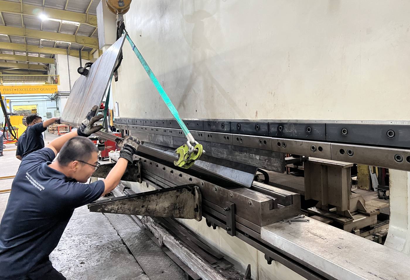
- Bending (Press Brakes): One of the most common forming operations, press brakes use a punch and die to create precise angles and curves in sheet metal. The ability to control bend angles and radii is critical for product functionality and aesthetics.
- Stamping: A high-volume manufacturing process that uses a press to force a die into a sheet metal blank, creating complex 3D shapes. This can include operations like coining, embossing, and drawing.
- Folding: Similar to bending but often refers to more automated processes where a sheet is clamped and a blade folds the material to a programmed angle.
- Rolling: Used to create cylindrical or conical shapes by passing sheet metal through a series of rollers.
- Deep Drawing: A specialized stamping process where a flat sheet metal blank is drawn into a die cavity, forming a cup-like or other deeply recessed shape.
Joining and Assembly
After individual components are formed, they often need to be joined together to create a complete assembly.
- Welding: A permanent joining method that fuses two or more metal pieces by applying heat, pressure, or both. Common welding processes include MIG (Gas Metal Arc Welding), TIG (Gas Tungsten Arc Welding), and Spot Welding, each suited for different materials and applications.
- Riveting: A mechanical fastening method where a rivet is inserted into a pre-drilled hole and deformed to create a permanent joint.
- Screwing/Bolting: Non-permanent mechanical fasteners that allow for disassembly or adjustment.
- Adhesive Bonding: Using specialized industrial adhesives to join components, often used where welding might compromise material properties or aesthetics.
For a foundational understanding of the overall concept, one might consult a resource like What Is Sheet Metal Fabrication, which provides a broader definition.
Stage 3: Post-Processing, Finishing, and Delivery – The Final Touches
The final stage of the sheet metal fabrication process focuses on refining the fabricated parts, enhancing their appearance, improving their functional characteristics, and preparing them for their ultimate destination.
Cleaning & Deburring
After cutting and forming, metal parts often have sharp edges (burrs) or residue from lubricants and coolants. Deburring removes these rough edges, improving safety and the part's fit and finish. Cleaning ensures surfaces are free of contaminants before any finishing treatments. Common methods include grinding, tumbling, sanding, and chemical cleaning.
Heat Treatment
Heat treatment processes involve controlled heating and cooling cycles to alter the physical and mechanical properties of the metal. These are not always necessary but can be critical for certain applications:
- Stress Relieving: Reduces internal stresses built up during fabrication, preventing warping or cracking.
- Hardening: Increases the hardness and strength of the metal.
- Annealing: Softens the metal, making it more ductile and easier to work with, or relieving cold work stress.
- Tempering: Reduces brittleness after hardening, increasing toughness.
Surface Finishing
Surface finishes are applied for various reasons: to enhance aesthetics, improve corrosion resistance, increase wear resistance, or provide specific electrical or thermal properties.
- Powder Coating & Painting: Applies a durable layer of paint or a dry powder that is then cured under heat, offering excellent protection against corrosion and a wide range of colors.
- Anodizing: An electrochemical process primarily for aluminum and its alloys, which thickens the naturally occurring oxide layer, enhancing corrosion resistance, wear resistance, and allowing for various dye colors.
- Plating (e.g., Zinc, Nickel, Chrome): Involves depositing a thin layer of another metal onto the surface, typically for corrosion protection (like zinc plating), improved hardness, or aesthetic appeal (like chrome plating).
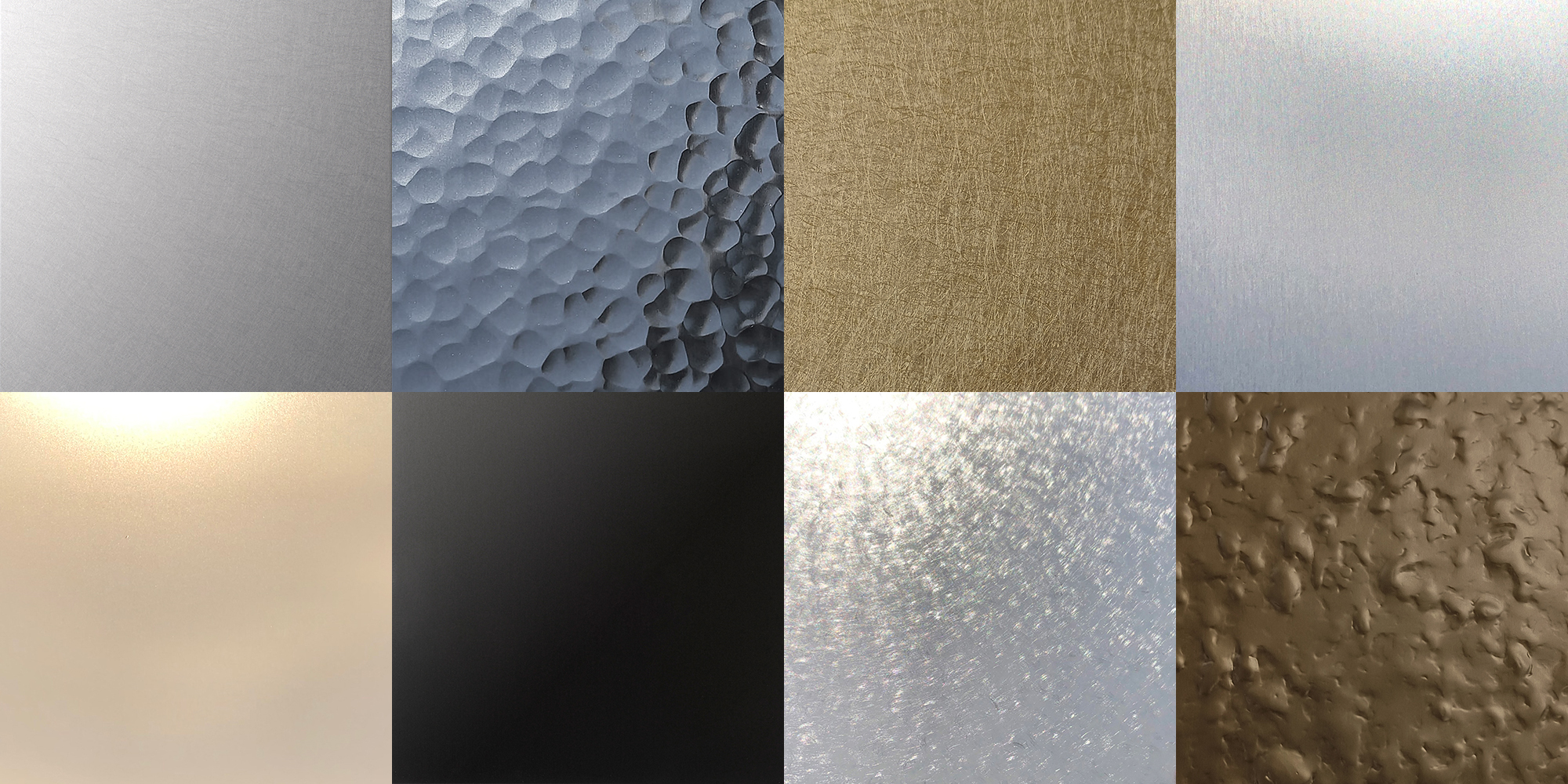
- Polishing & Brushing: Mechanical processes used to achieve a smooth, reflective (polished) or directional textured (brushed) surface for aesthetic purposes.
- Bead/Shot Blasting: Uses abrasive media propelled at high speed to clean, deburr, or create a uniform matte finish on the surface.
Quality Inspection
Throughout the entire process, and especially at the final stage, rigorous quality inspection is performed. Fabricated parts are meticulously checked against the original design specifications, tolerances, and quality standards. This can involve dimensional measurements, surface finish inspection, material integrity checks, and functional testing to ensure the part meets all requirements before it leaves the facility.
Packaging & Delivery
The final step is to carefully package the finished products to prevent damage during transit. The packaging methods vary depending on the product's size, fragility, and destination. Once packaged, the parts are delivered to the customer, completing the comprehensive sheet metal fabrication process.
Optimizing Your Fabrication Project
The efficiency and success of a sheet metal fabrication project hinge on a combination of factors, including skilled operators, advanced machinery, and meticulous planning. Modern fabrication heavily relies on Computer Numerical Control (CNC) machinery, which, guided by precise digital designs, enables highly accurate execution of complex cutting and bending operations. This automation not only boosts precision but also significantly increases production speed and consistency. Continuous improvement in fabrication processes, driven by technological advancements and refined methodologies, helps to reduce waste, optimize material usage, and shorten lead times. Engineers and manufacturers consistently seek innovative ways to streamline operations, from integrating smart factory concepts to refining tooling designs, all to ensure the delivery of high-quality products.
Frequently Asked Questions
What is the sheet metal fabrication process?
The sheet metal fabrication process is a manufacturing method that transforms flat sheets of metal into finished parts, components, or assemblies. It typically begins with a digital design phase, proceeds through various physical operations such as cutting, forming, and joining, and concludes with post-processing, finishing, and delivery. This comprehensive workflow ensures that raw metal is precisely shaped and treated to meet specific functional and aesthetic requirements for a wide range of industries.
Conclusion
From the initial concept sketched in a designer's mind to the final product delivered to a customer, the complete sheet metal fabrication process is a testament to precision engineering and advanced manufacturing capabilities. It’s a journey that converts raw metal sheets into the critical components that underpin countless industries and technologies. Understanding each stage – from the digital accuracy of design and engineering to the transformative power of core fabrication and the refining touches of post-processing – reveals the intricate blend of technology, expertise, and attention to detail required. As technology continues to evolve, so too will the methods and capabilities of this vital industrial process, prompting continuous exploration into its specific techniques and material innovations.
